|
Calculating Pressure Drop in Chilled Water Circuits
Technical Article No 1Author: Bruce Wernick PrEng. BScEng. Last Updated: 17 July 2007 If you have ever had to design a condenser or chilled water pipe system then you will have had to calculate the total circuit pressure drop in order to select the pump head. I have done a number of these calculations by hand and every time, I have had to search for my fitting pressure drop tables and manually calculate the pressure drop in each of the fittings. There is now a computer package available that will take all of the drudgery out of this process. The program has the advantage that it can offer you the following additional useful information.
Later I will discuss each of the above points, but now, we will go through the basic design process. The circuit shown in Figure 1 is a typical chilled water circuit that you could be faced with. This installation has a single screw chiller with a duty and standby pump set. There are three air handlers in parallel off the main chilled water supply, each with a balancing valve and a 3-way mixing valve. Figure 1. Chilled water pipe circuitThe initial problem of selecting a pump is to calculate the pressure drop in the index circuit. This is the pressure drop of the circuit with the highest pressure drop since this controls what the pump works against. Selecting pipe sizeThere is no theoretical limit to water flow rate in a pipe. If you have zero flow, there will be zero pressure drop. As you increase the flow, the pressure drop will increase as the square of the water velocity. According to the Darcy Weisbach equation, the pressure can be expressed as a function of friction factor and fluid velocity. Where dp Pressure drop, Pa r Fluid density, kg/m3 L Pipe length, m V Average fluid velocity, m/s D Pipe inside diameter, m The friction factor is the unknown in the above equation. This term is a bit more complicated but can be easily read off the Moody diagram. Figure 2. Moody DiagramGiven a Reynolds number and pipe roughness, you can determine the operating point on the Moody diagram and therefore the friction factor. On the Moody diagram, you will see that depending on the Reynolds number and surface roughness there are an number of flow zones. No single equation can therefore be used to calculate the friction factor. In the transition zone between hydraulically smooth and fully turbulent, the friction factor is given by the Colebrook equation. Where Re Reynolds number,
dimensionless = f D'Arcy friction factor, dimensionless e Pipe roughness, m D Pipe inside diameter, m v Velocity, m/s r Density, kg/m3 u Dynamic viscosity, kg/m·s While the above equations are technically correct, airconditioning engineers have traditionally made use of simplified charts as shown in Figure 3. This gives the pressure drop rate of a nominal schedule 40 steel pipe diameter based on 20C water for a given flow rate. In practical airconditioning systems, pipe size selection and maximum flowrate is governed by noise and pipe abrasion. Typical limits are as follows.
Figure 3. Pressure drop for water in schedule 40 steel pipe (water at 20°C)Calculating fitting pressure dropA convenient approach in calculating fitting pressure drop is to express each fitting in terms of its equivalent length of straight pipe of the same diameter. This would allow you to use Figure 3 to determine the pressure drop. There are many references that give equivalent lengths of fittings and valves. The ones used here are published by the Crane Company in technical report 410. Calculating circuit pressure drop by computerWe are often forced by time constraints to find shortcuts but don't want to sacrifice accuracy. After doing a number of these calculations by hand and on spreadsheet, I came to the conclusion that there could be many benefits to a program that would automate the process. The PipeFlow program has been developed to allow the airconditioning designer to do a quick and accurate pump selection with very little effort. The water circuit shown in Figure 1 can be entered into the program and solved in less than 20 minutes. The clear advantage here is that you now have an accurately calculated pressure drop that can easily be modified as the design requirements change. The basis of the program is to build up a table of pipes and fittings from the index circuit, as shown in Figure 4. This is the circuit with the largest pressure drop and is the one that controls the pump selection. Figure 4. PipeFlow Main Entry FormA database of all the commonly used fittings and valves has been developed with loss coefficients as published in Technical Paper 410 from Crane Co. These have been supplemented where necessary with data from The Chemical Engineers Handbook and are used to calculate the pressure drops shown in Figure 4. Building the pipe circuit is simply a matter of selecting a pipe or fitting from a list of pre-defined fittings. To cater for the known pressure drops, such as a chiller, the program has a user-defined type that allows you to specify the pressure directly. Entering a new circuitWhen the program starts up, you will see a spreadsheet with one empty line. At this point, you could go to the main menu and open an existing file or enter a new pipe circuit from scratch. To enter a new item, press the insert key. When you do this, an entry form as seen in Figure 5 appears that will let you specify what you want to insert. Figure 5. PipeFlow Entry FormTypically, if you are entering a new system, you will have a schematic and know the design water flow in each branch. A convenient starting point is the pump. Enter the pump flow rate and press the AUTOSIZE button. The program will now calculate the main pipe size. Now, add all the pipes and fittings of this diameter to the circuit table. Each of these types has further options. For example if you want to add 4 off 90º elbows, go to the standard fittings page, enter the quantity and select the elbow from the fitting list. To complete the circuit, do the same for the pipe section after the first take off and continue until the whole circuit has been added. Don’t worry about making mistakes because any branch can be edited or deleted in the main table. Don’t forget to save your work. The program has a quick save button, so to avoid loss of data, use it regularly. At any time, you can load saved circuits into the table. Entering multiple circuitsIn airconditioning piping systems, you will often have to find the pressure drop in parallel water circuits. This program calculates the pressure drop in the index run only. To assist in determining the index run, items in each parallel path can be grouped. The program offers a grouping option where you can assign a unique number to each new group. Now you can specify whether the group falls in the index run by assigning the number ‘1’ to the group value. Be aware that if the Group option is not activated, all branches are assumed to be included in the index run. Solving and viewing resultsViewing the results is now simply a matter of paging through the table shown in Figure 4. There are many features that make analysis of the results easier. The first of these is that any of the table columns can be sorted in ascending or descending order by clicking on the column heading. The obvious choice here would be to sort on pressure drop and check the highs and lows for input errors. Some of the other features are described in the next section “Dealing with errors”. Figure 6. Typical PipeFlow ReportOnce you are satisfied with the results, you can obtain a hard copy by printing a report as shown in Figure 6. Press the PREVIEW button and an image of the printed page will appear. You can now set margins and print font etc and send to the printer for a hard copy. Dealing with errorsThe only real problems when designing a pipe network is under sizing or over sizing the pipe diameter. Under sizing will lead to excessive pressure drops, noise and a badly balanced circuit. Over sizing will lead to over pricing and also to a badly balanced circuit. In this program, you can define the design limits. If any item falls outside the design limits, the pressure drop will be highlighted. You can then select each problem branch and edit it manually. A special feature has been added here where all the errors can be dealt with together. Select the VIEW WARNINGS menu option and a list of all warnings will appear with more details of the nature of the problem. Obviously, the program cannot make engineering decisions but some problems can be fixed automatically. If you select a problem branch, and press the AUTOFLOW button, the flowrate will be revised to the maximum design flow for the existing diameter. If you press the AUTOSIZE button, the pipe size will be changed such that the pressure drop rate will be less than or equal to the maximum rate. Calculating a price estimateThis is a feature that has been added to allow you to generate a quick price estimate. Each item is priced on the basis of a cost and labour table using the following equation. Price = Quantity · ( ItemCost + LabourCost · InstallTime) The accuracy of this budget depends entirely on the pricelist values that you enter. To improve your job costing, include all associated material costs. For example, with a valve, include the cost of gaskets, mating flanges and bolts. For pricing purposes, the complete network must be entered as shown in Entering multiple circuits above. Other program featuresThe PipeFlow program makes use of many of the new programming techniques and will run on any computer that runs Windows 9.x, 2000 and Windows NT. The following are some of the additional program features provided.
Figure 7. Pipe Friction Factor Calculator
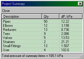
Figure 8. Project Summary Form
ConclusionThe PipeFlow program is a comprehensive circuit pressure drop calculator. Its ease of use, accurate calculation and error checking features make it an invaluable tool for the airconditioning designer. References
|